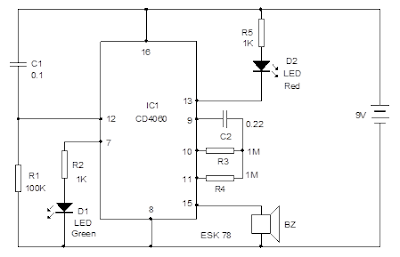
This circuit can be used as a simple timer and it gives beeps when the timing cycle ends. It is designed as a 4 minute timer.
IC CD4060 is used as the timer with the timing components C2
and R3. With the given values of C2 and R3, the output pin 13 becomes high and
Red LED turns off indicating half time. When the pin15 turns high after 4
minutes buzzer beeps indicating the time out.
At power on, IC1 resets through C1 and R1 and starts
oscillations. The oscillations are indicated by the blinking of Green LED. The
Red LED also turns on since the output pin 13 is low. This output turns high
after 2 minutes and Red LED turns off. After 4 minutes, pin15 turns high and
buzzer beeps. The timing can be changed by increasing or decreasing the value
of either C2 or R3.
Note
If component removal is required for re assembling, do not
bend the excess leads of components before soldering. Cut the excess lead close
to the PCB and apply some flux. Apply little solder at the contact point. Do
not apply, excess solder or over heat the solder points. PCB tracks will
detach. Clean the surface with kerosene, or PCB cleaning fluid to remove flux
and dirt.
COUNT DOWN TIMER
This circuit can be used as a simple timer and it gives beeps
when the timing cycle ends. It is designed as a 4 minute timer.
IC CD4060 is used as the timer with the timing components C2
and R3. With the given values of C2 and R3, the output pin 13 becomes high and
Red LED turns off indicating half time. When the pin15 turns high after 4
minutes buzzer beeps indicating the time out.
At power on, IC1 resets through C1 and R1 and starts
oscillations. The oscillations are indicated by the blinking of Green LED. The
Red LED also turns on since the output pin 13 is low. This output turns high
after 2 minutes and Red LED turns off. After 4 minutes, pin15 turns high and
buzzer beeps. The timing can be changed by increasing or decreasing the value
of either C2 or R3.
Note
If component removal is required for re assembling, do not
bend the excess leads of components before soldering. Cut the excess lead close
to the PCB and apply some flux. Apply little solder at the contact point. Do
not apply, excess solder or over heat the solder points. PCB tracks will
detach. Clean the surface with kerosene, or PCB cleaning fluid to remove flux
and dirt.


